The science of corsetry and creating a perfect made to measure pattern (part 2)
Posted on
So in part 1 I introduced the concept of how I am using AutoCAD and an excel spreadsheet to design a made to measure corset pattern for myself. In this second part I will update on the progress I am making. So far so good, however I am yet to see what it looks like on the body - I should have some photos of the final corset in part 3 to follow.
The measurements involved included;
- Full bust (fb)
- Underbust (ub)
- Low rib (lr)
- Waist (w) minus desired reduction (2’’)
- High hip (hh)
- Low hip (lh)
- The vertical distances between each of the above points
I first created different worksheets for 12, 16, and 20 panel patterns in excel, converted my measurements into mm, divided this by 2 so I would be working on just one side of the corset, and subtracted the desired back gap and waist reduction from these measurements. When divided by the number of panels on each side, this gave me an equal dimension per panel – I then ‘weighted’ these measurements according to whether this would be at the bust or bum etc. After quite a bit of other jiggery pokery including adding extra millimetres to the back and front panels to accommodate the hardware, and evening out the middle sections, I ended up with a table of figures that looked about right for the 8 panels that will form one side of the corset;
|
front |
back |
|
|||||||
|
Panel 1 |
Panel 2 |
Panel 3 |
Panel 4 |
Panel 5 |
Panel 6 |
Panel 7 |
Panel 8 |
Total mm |
|
|
69 |
59 |
53 |
47 |
47 |
41 |
41 |
67 |
425 (fb) |
|
|
57 |
47 |
41 |
41 |
41 |
41 |
41 |
67 |
375 (ub) |
|
|
57 |
43 |
37 |
37 |
37 |
37 |
37 |
67 |
355 (lr) |
|
|
57 |
36 |
30 |
30 |
30 |
30 |
30 |
67 |
309 (w) |
|
|
57 |
47 |
41 |
41 |
49 |
49 |
49 |
75 |
410 (hh) |
|
|
55 |
45 |
39 |
47 |
47 |
56 |
56 |
82 |
425 (lh) |
|
|
|
|
|
|
|
|
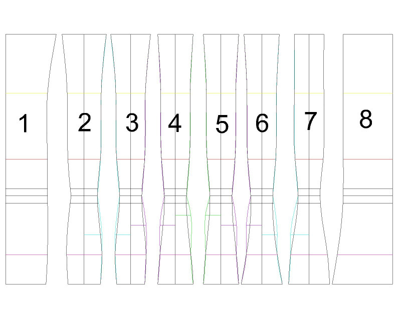
In AutoCAD it was then just a simple task of adding these horizontal lines onto a vertical line that corresponded to the vertical line measured from full bust to low hip. Using a combination of spline lines, arcs and straight lines I joined up the horizontals making amendments to ensure some hip spring was included. You can see how I have pushed out a hip spring by drawing the spline line to an additional point in pieces 2 (one side), 3, 4, 5, 6 and 7 (one side). I increased the curvature towards the middle pieces where the curviness works better by snapping the line to a point equivalent to the high hip at a point offset at 33.3% between the waist and high hip (green line). Similarly, points at 50% (purple line) and 66.6% (blue line) gave the snap point for the lesser spring hip curves to the other panels. I offset the waist line to indicate where a 20mm waist tape would sit. This part of the process was very quick – no more than 15 minutes. I like how the software creates beautiful curves – a French curve ruler produces similar shapes of course but the manual drafting process would never produce something as repeatable and exacting as the CAD drawing functions.
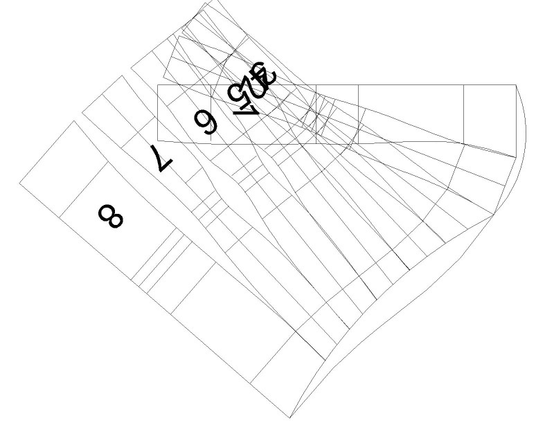
I then rotated the individual pattern pieces so they matched at the top and arced a line corresponding to the sort of top line I would like - a sweetheart neckline and dipping under the arm pits and leaving a high back;
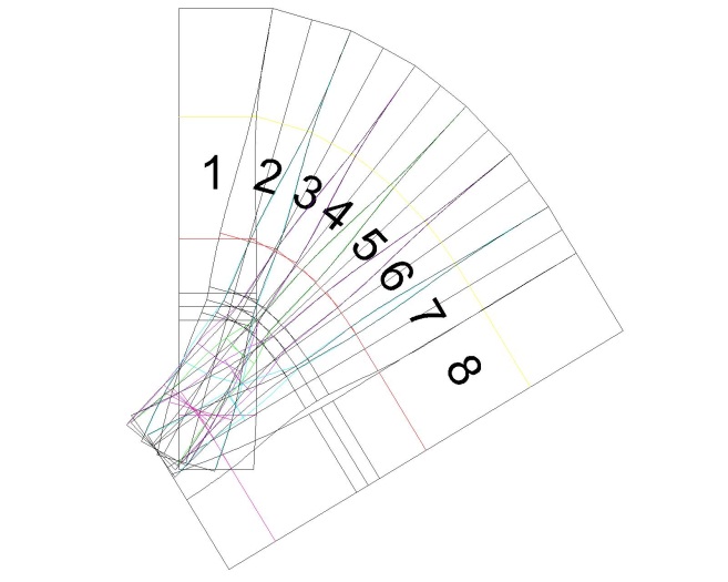
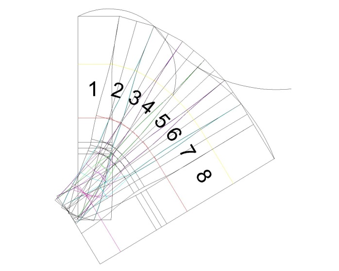
Trimming the top line according to the arc and separating the pieces you can see how they will match up;
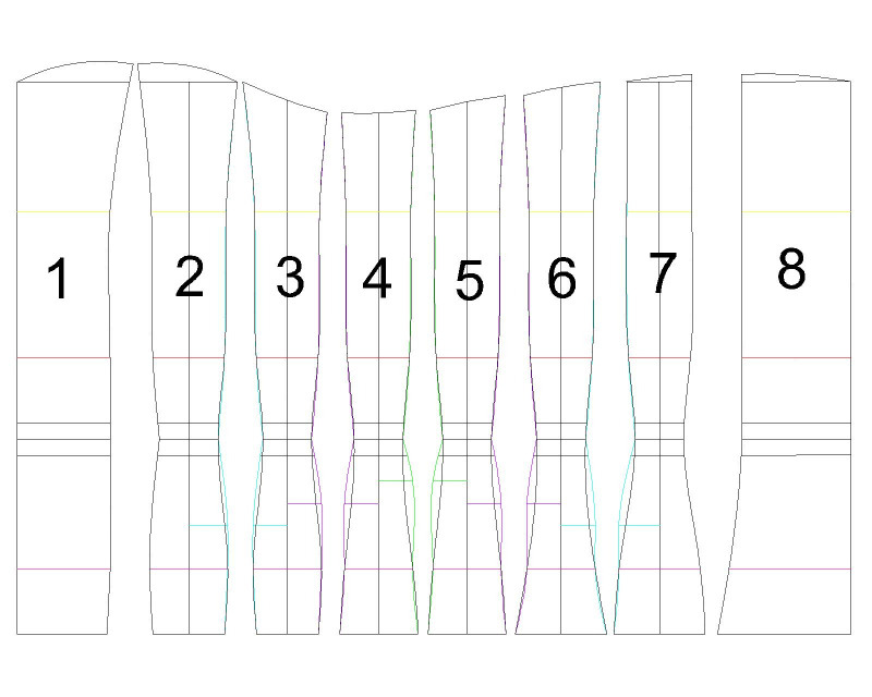
I left the bottom knowing that I could always do the same to this side if I wanted a different shape. This part of the process was a little more fiddly but still only about another 15 minutes to curve the one side. If I were to spend another 15 minutes rotating the bottom sides to match up and then arcing a curving bottom line I estimate that the entire process, from plugging in the eleven measurements into my spreadsheet and then drawing out the pattern in AutoCAD, would take no more than one hour. A lunch-break project!
In the next and final part of this project I will make up the toile.
